Thermal Bridging Solutions: Improving Building Envelope Performance - Armatherm, a Brand of Armadillo Noise & Vibration Limited

Please contact us via contact@construction-cpd.com to get permission to publish this video on your website.
<div style="position: relative!important; width: 100%!important; min-height: 700px; overflow: hidden!important; padding-top: 56.25%!important;"><iframe src="https://www.construction-cpd.com/cpd-external-view?ExternalId=47&ReturnUrl=https://www.construction-cpd.com/thermal-bridging-solutions-building-envelope-performance-cpd" style="position: absolute; top: 0; left: 0; bottom: 0; right: 0; width: 100%; height: 100%; min-height: 500px; border: none;" mozallowfullscreen webkitallowfullscreen allowfullscreen></iframe></div>
Welcome to thermal bridging solutions improving building envelope performance sponsored by Armatherm. Armatherm sponsors this program provided by RIBA as a CPD. Certificates of completion are available for self-reporting and recordkeeping needs upon completion of the program. This program is registered with RIBA for continuing professional education. As such it does not include content that may be deemed or construed to be an approval or endorsement by the RIBA of any materials of construction or any method or manner of handling, using distributing or dealing in any material or product. Questions related to the information within this programme should be directed to Armatherm upon completion of this program.
Login to record your CPD points

This presentation is protected by UK and International Copyright laws. Reproduction, distribution, display and the use of the presentation without written permission from Armatherm is prohibited.
Thermal Bridging Learning Objectives
Thermal bridging is a big concern in the building industry. It has been recognised as a significant factor in building envelope heat loss by reducing heat flow through a buildings thermal envelope we can reduce energy consumption as well as prevent potential condensation issues.
Building codes have increased requirements of building enclosures requiring continuous insulation without thermal bridging. Thermal break materials can be used to reduce heat loss in wall assemblies, transitions and structural connections throughout the building envelope. They can minimise building energy loss and improve building envelope performance. This course will provide an overview to thermal bridging, discussing the reasons why it occurs as well as how it can be prevented. This course will also compare building details with and without thermal break solutions, to highlight the importance of determining accurate values of thermal transmittance.
By the end of this online learning module you should be able to define thermal bridging, describe why thermal bridging occurs, explain the effects of thermal bridging, describe how to calculate effective wall assembly U values, describe the different solutions available to prevent thermal bridging.
What is Thermal Bridging?
So, let's start off by looking at what exactly thermal bridging is. Thermal bridging occurs when structural elements that transfer load from outside the envelope to the main structure and penetrate the thermal envelope. The envelope of a building provides a thermal barrier between the exterior and interior, keeping out moisture as well as resisting the flow of heat through the wall. A thermal bridge also known as a cold bridge or heat bridge is an area of an object often a building which has a significantly higher heat transfer than the surrounding materials. This results in an overall reduction in thermal insulation of the object or building. Examples of where thermal bridging can occur are canopy's, balconies and cladding attachments. We will look at some of these examples in more detail later on in the course.
How is Thermal Bridging Identified?
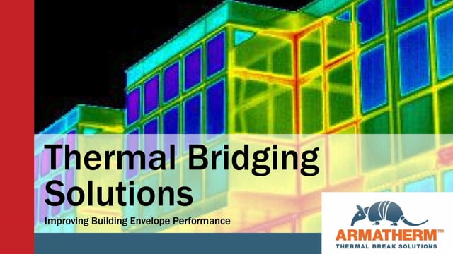
Thermal imaging cameras are used to identify thermal bridges in the building industry. In these examples the thermal bridges appear as areas of higher temperatures when viewed from the outside of the building. So, you can see the area of the balcony, around windows and at other interface details are, where the thermal bridges occur, as there is a higher heat transfer through these assemblies. To help us better understand thermal bridging we'll take a look at some of the commonly used key terms and their definitions.
Thermal envelope
Thermal envelope is a term used to include all building elements that totally encased the heated or cooled spaces of a building to resist heat flow between the interior and exterior. So, everything that separates the inside living space from the outdoors, this includes the walls, roof, slabs on the ground, insulation, weather stripping, caulking, windows and doors.
Thermal break
Thermal break, this is an element of low thermal conductivity placed in a system or assembly to reduce or prevent the flow of thermal energy between conductive materials.
Thermal conductivity
Thermal conductivity (K) is the amount of energy and material will conduct in heat through 1 square metre of structure with 1 degree Celsius of temperature difference. This K value is the rate of heat flow through a material. The R value or thermal resistance to heat flow of a material is equal to the material thickness divided by its K value.
Area waited calculations
Area waited calculations are commonly used to calculate R & U values of wall assemblies. Typically, this is done by weighting the heat flow through the materials by the area they take up. Using the physical area of a thermal bridge assumes the heat flow path through a detail is 1 dimensional and parallel. However highly conductive building materials create lateral or multidirectional heat flows to other components that are not accounted for in parallel heat flow assumptions. Parallel heat flow path assumptions and area waiting do not accurately define the effects of a thermal bridge.
U Value
U value measures the rate of heat flow through an assembly area per unit temperature. The lower the U value the more energy efficient the assembly will be.
R Value
R value measures a material's resistance to heat flow, so it tells you how well a certain construction material insulates.
Linear and Point Transmittances
Linear and point transmittance ease along with clear field transmittance can be used to determine the overall heat flow for any size wall or roof by calculating effective R & U values that include the effects of thermal bridging.
Clear field transmittance
Clear field transmittance is the heat flow through a wall roof or floor assembly which includes the effects of uniformly distributed thermal bridging components such as brick ties, cladding attachments or framing studs. The clear field transmittance is a heat flow per area.
Linear transmittance
Linear transmittance is the additional heat flow caused by details that can be defined by a characteristic length. This includes slab edges, parapets, corners, shelf angles, masonry supports and transitions between assemblies. The linear transmittance is a heat flow per length.
Point transmissions
Point transmissions is the additional heat flow caused by thermal bridges that only occur at a single location, this includes canopy's, balconies, windscreens, davits and intersections between linear details. The point transmittance is a single additive amount of heat loss.
Why is Thermal Bridging a Concern?
Let's now take a look at examples of thermal bridging. Conductive heat transfer through the building thermal envelope creates significant energy losses. In order for us to be able to design and build more energy efficient buildings, we need to address the thermal performance of the building enclosure. Hot box measurements show thermal bridges in conventional construction may reduce isolation effectiveness by as much as 50%, resulting in wall assemblies and interface details that do not meet current energy code requirements for minimum U values. Simply adding insulation to walls has proven to not actually decrease the energy use of a building. Thermal bridges allow heat to bypass the insulation, contradicting any benefit of having more insulation in the wall.
Thermal Bridging Facts
Let's now look at some facts. Thermal bridges are inefficiencies within the envelope structure of a building, where heat is transferred at a much higher rate than through the surrounding envelope area. Thermal bridging can reduce the R value of a wall assembly by as much as 70%. The total heat flow through typical wall assemblies is underestimated by as much as 20 to 70% due to thermal bridging. Heating and cooling equipment is often oversized resulting in operational inefficiencies, which means significant energy consumption increases and costs for the building owner.
By using thermal bridging solutions, we can maximise energy costs by minimising the amount of heat transferred through the building envelope. Thermal break materials can be used to reduce heat loss in wall assemblies’ transitions and structural connections throughout the building envelope.
Examples of Thermal Bridging
There are many different examples of transitions and structural connections where thermal break materials can be used, reducing thermal transmittance and improving envelope U values. Some examples are masonry shelf angles, Z girt cladding attachment, balconies, roof penetration and parapets, wall to wall foundation transition.
Masonry Shelf Angles
Let's now take a look at some examples of thermal bridging in more detail. Masonry veneer walls require tie backs and shelf angles. Masonry supports, which form significant thermal bridges and can reduce the walls' R value by as much as 60% which makes it very difficult to meet energy codes. Shelf angles transfer the masonry load back to the buildings structural steel or the concrete slab edge. This in turn interrupts the continuous insulating layer of the wall assembly creating a continuous thermal bridge.
Concrete Balcony
Another good example to look at is a concrete balcony. A concrete balcony that extends the floor slab through the building envelope is an extremely common example of thermal bridging. In order to minimise heat flow and energy loss through the balcony slab, proper thermal break solutions need to be incorporated. For example, cantilevered type balconies can be approximately 3% of the total clear wall area of a building. However, 15 to 30% of the heat flow through the clear wall area is associated with balconies. So, in the case of a balcony heat moves from the floor structure through the wall because there is no thermal break in the floor. By using structural thermal break solutions balconies will avoid potential condensation and mould issues while keeping the interior space at the desired temperature.
Effects of thermal bridging
Now let's take a look at the effects of thermal bridging. Thermal bridging affects several aspects of building design. One of the biggest issues is that it reduces the overall energy efficiency of a building, resulting in higher energy consumption. Because of the reduced energy efficiencies HVAC systems need to be oversized, which causes operational inefficiencies. Thermal bridging can also cause condensation which can corrode metal and deteriorate concrete.
Condensation
Let's look at condensation in more detail.
So, what causes condensation and why is it such a big concern? As well as creating a breach in heat flow, thermal bridges can reduce the surface temperature on internal surfaces as they penetrate the thermal envelope. This can result in potential moisture problems. Overtime moisture within the building structure can corrode metal, rod, wood, deteriorate concrete and allow mould to grow. In cold climates moisture can collect on the internal surfaces of exterior walls, when these surfaces become too cold, due to a thermal bridge, the relative humidity of the air could exceed 65%. The higher the relative humidity the greater the water vapour content. Condensation will occur on cold surface areas when the temperature at the internal surface of an external wall is at or below the dew point temperature of the air.
How can condensation in the building envelope be prevented?
Thermally efficient building envelopes using both thermal break materials and vapour barriers will help reduce the risk of condensation by forcing the dew point out of the thermal envelope. A thermally broken structural connection will prevent excessive heat flow and potential condensation problems.
Assessing the Condensation Risk
Using the temperature index TI is the best way to assess condensation risk and prevent the negative effects associated with it. The TI can be used to predict if condensation will occur by comparing the coldest interior surface temperature, to the dew point temperature. Condensation will occur if the interior surface temperature is less than the dew point temperature. The temperature index is the ratio of the temperature difference between the inside surface temperature and the outside air temperature, divided by temperature difference between inside and outside air.
Quantifying the effect of thermal bridging
In order to be able to address heat loss issues you need to be able to quantify the impact of heat loss on building performance. This will help reduce costs and energy consumption. As well as improving the performance of the building envelope. So how can you best quantify the impact of heat loss on building performance?
Measuring Thermal Performance
Let's now look at how you can use the effective R & U values to accurately measure the thermal performance. Linear and point transmittance along with clear field transmittances can be used to determine the overall heat flow for any size wall or roof by calculating effective R & U values that include the effects of thermal bridging. For whole building load calculations, the linear and point transmittances are simply added to the clear field U value of a given assembly area to calculate the overall thermal transmittance.
Thermal Break Solutions
We have looked at what causes thermal bridging and the damaging effects it can have, so now we'll look at what solutions are available to improve the building envelope performance. There are several different ways to achieve this:
- Attention to design of a building structure as well as selecting the correct materials to use, helps create a uniform thermal resistance such as thermal brakes and continuous insulation.
- To be able to design and build more energy efficient buildings, we need to address the thermal performance of the building enclosure.
First, let's look at what materials you should and shouldn't use to prevent thermal bridges.
Thermoplastics
Thermoplastics such as nylon, PVC and Teflon as well as rubber materials such as neoprene, and nitrile can have low thermal conductivities. This is good but these materials deflect creep and take a permanent set under load. In a structural connection this is not suitable so other materials should be used. Compare this to thermoset materials such as polyurethanes and epoxy resins.
Thermosets
Thermosets are ideal for use as thermal breaks because they are much more resistant to creep and deformation under load, while also having low thermal conductivities. Epoxy or phenolic thermoset resins have the additional advantage of not melting or dripping when exposed to fire.
Low thermal conductivity materials vs High Strength Materials
Materials with low thermal conductivities can be manufactured, engineered from a wide array of plastic composites and elastomeric or foam based compounds. In thermally broken structural connections such as cladding attachments, canopies and balconies, materials used as thermal brakes must have high compressive strength, stiffness and resistance to creep. Typically, high strength materials tend to have high thermal conductivity values, whereas low strength materials tend to have low thermal conductivity values. The most effective thermal break solutions will need to have sufficient strength for structural support and dimensional stability as well as a low thermal conductivity capable of reducing heat flow and preventing a thermal bridge.
Thermal Break Solutions Comparisons
On screen now you will see different examples of building interface details with and without thermal break solutions. These details highlight the standard bolt through connection method of the Armatherm thermal break for a masonry support application. With the thermal break being situated between the shelf angle and the building steelwork it is good practice to include a thermal washer and bushing to minimise the thermal bridging to a greater extent. Looking at the shelf angle you can see that the R value and consequently the U value of wall assembly decreased by 50%, when including the effect of the slab edge and shelf angle. This shows that half of the heat loss in this wall assembly is due to the shelf angle. Now compare the values when the thermal break solution is used behind the shelf angle. The R value is increased by 28%, while the heat flow per unit length linear transmittance is reduced by 57%.
Balcony Canopy
Balcony canopy connections that pass through the exterior insulation and air barriers can reduce a walls R value by as much as 60% due to thermal bridging of these highly conductive framing elements. Using a structural thermal break solution at the connection within the thermal envelope, will improve the effective you value of the wall assembly and reduce heat loss by as much as 60%. The structural thermal break material must be capable of transferring the loading in moment and shear connections without creating significant rotation. It is important that any selection has undergone structural testing for moment and shear connections for creep as well as the rotation and any impact on bolt force. It is a significant factor that while minimising heat flow the structural performance of these connections must remain acceptable.
Point Transmittance Roof Davit
The roof is part of the building envelope where structural connections for Davit’s anchors and dunnage supports extends through the insulation creating potential condensation problems. The R value of a roof can be reduced by up to 40% in these areas. A thermal break at these locations will improve the U value of the roof assembly and prevent potential condensation problems at the structural connection. Unlike lightweight roof insulation selecting the correct structural thermal break material, can transfer the loading conditions at these locations while significantly reducing heat flow. The transmittance can be improved by as much as 80%.
Foundation to Wall Transition
At the intersection at a slab on grade to foundation wall and the exterior wall to foundation transition are both areas where heat flows out of a building due to primarily non continuous insulation details. The linear transmittance at these locations can be reduced by as much as 60% by using an efficient structural thermal break. Products satisfying this would be ultra-high density PU foams, manufactured in several densities to provide a range of load capacities with R values as low as R 3.8 per 25mm of thickness.
It has been demonstrated that metal zed girts are responsible for 45% to 50% of the heat flow through conventional steel stud wall assemblies with exterior cladding. Adding layers of insulation is not effective enough in creating effective U values that meet current energy codes. Using non-conductive clips and girts makes the exterior insulation up to 98% efficient, reducing heat loss and improving the clear field U value of the wall assembly. The theoretical R value of a wall assembly can be reduced by as much as 60% when the effective steel Z girts is added to the calculation. Replacing the steel short circuit with a fabric reinforced phenolic resin Z Girt brings the complete wall assembly back to almost 95% efficient.
In Summary
- Thermal bridging is a problem that is becoming more recognised and is being taken seriously.
- In order to change current practice for dealing with thermal bridging communication between all members of the design team is essential.
- In the past the effects of thermal bridging were difficult to define. In addition to the heat flow normally transmitted through the building envelope, air leakage for example multi directional heat flows are created at thermal bridge locations. Therefore, the use of effective R & U values rather than nominal values is a more accurate measure of thermal performance.
- By properly identifying all of the inefficient aspect of a building structure and by using thermal break solutions, thermal bridging can be prevented. This could result in reduced heat loss by as much as 70%, as well as reduced cost and energy consumption, all while improving the performance of the building envelope.
Thank you for your interest in thermal bridging solutions to improve building envelope performance, sponsored by Armatherm.
For more information please contact www.armatherm.com.