Condensation in the roofspace - A Proctor Group

Please contact us via contact@construction-cpd.com to get permission to publish this video on your website.
<div style="position: relative!important; width: 100%!important; min-height: 700px; overflow: hidden!important; padding-top: 56.25%!important;"><iframe src="https://www.construction-cpd.com/cpd-external-view?ExternalId=41&ReturnUrl=https://www.construction-cpd.com/reducing-condensation-in-the-roofspace-cpd" style="position: absolute; top: 0; left: 0; bottom: 0; right: 0; width: 100%; height: 100%; min-height: 500px; border: none;" mozallowfullscreen webkitallowfullscreen allowfullscreen></iframe></div>
Background
Innovation runs through the Proctor family since its earliest records, dating back to the 1600’s. The family originally manufactured textiles and supplied flax to Scotland’s mills. This progressed to agricultural products, then finally to the supply and fabrication of insulation products in the 1960’s.
Throughout the 1960s and 70s, Alistair Proctor and his brother Herbert grew this small family business into a nationwide supplier. Joining the group in 1982, Alistair’s son Allan Proctor continued this expansion, introducing a range of innovative vapour permeable membranes, all of which are still manufactured in Scotland today.
Login to record your CPD points

In the 1990’s, Allan Proctor - working closely with Universities, development centres, and most importantly customers – developed the company portfolio further. Today, the group’s diverse range of building and construction solutions also encompasses ground gas protection membranes for contaminated sites, acoustic solutions for refurbishment and new build developments, and natural timber cladding, treated to provide unrivalled warranties in both commercial and domestic applications.
In the early 2000’s, a focus on establishing export markets and global partnerships gave this once small family business a truly international presence, competing head to head with some of the largest manufacturers in the world. Such partnerships continue to be developed, supplying products with performance characteristics to rival many market leading manufacturers in a wide range of countries.
Since taking over in 2012, current Managing Director Keira Proctor has continued to build on the group's traditional values of trust, honesty, hard work and innovation from the very same desk where her father and grandfather once ran the organisation. Alongside consolidating the company’s market leading position, Keira has led the drive to expand into new market sectors worldwide.
By applying the groups extensive knowledge and experience with construction materials to other industries, strong links have been forged in the rail infrastructure and oil and gas markets, and the company is now driving towards automotive, marine and military sectors – modifying the unique properties of products utilised in buildings to provide solutions to the many different problems our diverse customer base faces.
HAMM
For any building to have an energy efficient, healthy, moisture free building envelope there is a clear need to manage the balance of Heat , Air and Moisture movement (HAMM) throughout the building’s life cycle from design, construction, completion and use.
Understanding the importance of these key elements on the building envelope is crucial to the successful construction and operation of a building. Architects, designers, and building product manufacturers must seek to ensure that they fully understand the science behind our buildings, managing the external and internal forces which impact on the quality of the completed building, its performance in use, as well as the health of its occupants and the wider environment.
The A. Proctor Group Ltd, have been developing vapour permeable membranes and vapour control layers for over 25 years, and can provide condensation control and air barrier solutions for all areas of the building envelope, across a variety of projects.
Condensation In The Roofspace
This presentation discusses the requirements for breather membranes, air barriers and vapour control layers, looks at the principals of condensation, the effects of condensation, issues of detailing cold pitched roofs i.e. insulation, ventilation and underlay. It also looks at condensation controlling measures and the solutions.
In this presentation, we’re going to take a look at condensation, what it is and what causes it, along with some of the design considerations and regulations involved. We’ll also take a look at the types of vapour permeable underlay available, and some of the differences in performance between them.
Roofshield - What is condensation?
So what is condensation?
Condensation is the formation of liquid water when warm humid air comes into contact with a cold surface.
The warmer the air in an environment is, the more water vapour it can retain. However when this moisture laden air cools down it’s capacity to retain water vapour reduces and this vapour will turn back into liquid.
The most common example of this is bathroom mirrors, where the warm air in the bathroom can support a lot of moisture, from, for example a shower, but when it hits the cold surface of the mirror it loses this ability, causing the mirror to “fog up”.
Examples of condensation.
As well as showers and bathing, there’s a number of other moisture sources present in buildings.
Cooking can produce a fair amount of water vapour, not only through the obvious source of water boiling in a pan, but also a byproduct of the combustion of certain gasses. Cooking can also raise the temperature of a room, which in turn can increase the humidity of the air.
Laundry is also a significant moisture source, both from steam irons, and drying out clothes. Clothes being hung over radiators to dry out is one of the most common causes of condensation and damp problems in housing.
Finally, the buildings occupants themselves produce a lot of moisture through breathing and sweating. Even while sleeping this represents a substantial source of moisture, and activities such as sports produce significantly higher moisture loads. When considering condensation control strategies, the activities taking place in the building are among the most important factors.
Another common example of condensation is a cold drink on a warm day, but how and where does condensation occur in the context of buildings?
Types of condensation.
In the habitable areas of the building, warm, humid internal air creates what is known as a vapour pressure. Vapour pressure is the driving force behind condensation risks in buildings.
In the UK, this process mostly works from inside to outside, pushing the moisture into the walls, floor and roof of a building, towards typically cooler and less humid conditions outside.
So how does this vapour pressure give rise to a condensation risk?
The insulation in the building fabric helps to keep the indoor temperature more or less constant, but as we move outward through the building element, the temperature will drop sharply across the insulation layer. As the temperature drops the air loses its ability to retain water vapour.
At a certain temperature, the air will become saturated and lose its ability to contain the water vapour. This temperature is known as the “dew point temperature” and is a product of the vapour pressure at a given point in the structure, as well as the vapour resistance of the individual layers in the construction.
Provided the actual temperature remains above the dew point temperature, there will be no significant risks of condensation occurring.
If the actual temperature drops low enough to coincide with the dew point, the air will become saturated, and condensation will occur at the point the temperatures meet.
The nature and severity of the condensation problems will be determined by the extent to which the temperature drops below the dew point, and where in the structure this occurs.
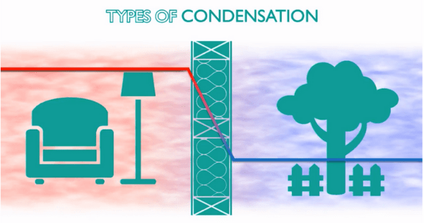
If the wall is cold and poorly insulated, the dew point will occur on the internal surface, which causes SURFACE CONDENSATION. This is fairly common in bathrooms and kitchens, particularly in older properties which may have solid brick or stone walls.
If the meeting point is within the fabric of the building element, this produces what is called INTERSTITIAL CONDENSATION.
This is most obvious in lofts with poor ventilation or low spec vapour permeable underlays, but it can also be hidden completely within the element. It's therefore important that designers ensure this does not occur as it may be invisible to the occupants.
It's also possible to have REVERSE CONDENSATION which occurs where the indoor conditions are cooler and less humid than conditions outside, in which case the normal vapour drive is reversed. It's very rare that this occurs in climates like the UK, however in some specialist applications such as cold stores it's worth bearing this in mind. It’s more common in warmer locations such as the middle east or southern US.
Condensation effects.
So now we’ve discussed what condensation is and how it occurs, let's take a look at some of the problems it can cause.
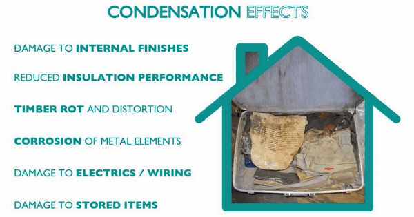
If condensation leads to persistent damp in a specific area, it can cause damage to the internal finishes. This damage can range from discoloration to the growth of mould spores. Mould spores within the habitable spaces of a building can give rise to serious health problems for the building occupants, particularly children, the elderly or anyone with respiratory problems.
Damp spots and any subsequent mould can be an indicator of cold spots, such as at junctions/corners, or areas where there is substantial cold bridging. Surface mould can also be an indication of poor air flow such as behind furniture, at the back of built in wardrobes or in specific areas of attic spaces.
Some insulation materials, particularly fibrous types like glasswool, will absorb moisture arising from interstitial condensation and, since water conducts heat better than air, this will reduce the insulation's performance.
If the dampness is caused by locally reduced temperature, such a cold bridge or air leak, this decrease in insulation performance will increase the rate at which further condensation will form, resulting in a vicious circle of degrading performance.
In most cases, timber will begin to rot if the moisture content is above 20% for longer than 60 days. Rotten structural timbers will severely reduce the lifespan of the building, so it’s critically important to ensure moisture is managed to avoid this.
It’s also important to remember that as timber absorbs moisture, it may swell and distort due to expansion. The converse is also true, if the timber gets wet and swells during construction, it may subsequently shrink as it dries, which can also lead to problems.
Although metal elements are generally more resistant to moisture damage than timber, they are not immune, and corrosion of metalwork can weaken structures. Corrosion damage to metal elements like roofing sheets can also lead to further moisture problems due to water ingress in adverse weather.
Water ingress into electrical services and network cabling will have obvious negative effects, but it’s also worth considering that any structural distortion due to swelling timber or corroded steel can also affect building services by over-stressing cables, pipes and conduits.
There are two principal issues associated with items stored in lofts, firstly, damp conditions can lead to damage due to mould growth or rot.
Secondly, items and boxes can block roof ventilation or obstruct airflow, which can lead to problems in otherwise well designed and constructed roofs. In this respect, non ventilated roofs are typically more robust over the long term as there are no ventilation openings to block.
Design considerations
We’ll now take a look of some of the factors affecting pitched roof design, and how we can design out condensation problems from the start.
The building fabric, typical weather conditions and the anticipated occupancy patterns and uses will all interact to define the moisture risks associated with the construction. These “ground rules“ must be identified and understood to form the basis of a good hygrothermal design strategy.
Once an understanding of the building, weather and occupancy is achieved, the designer can then focus on ensuring the heat, air and moisture movement within the structure is properly balanced. This ensures both a healthy environment for the buildings occupants and a long life for the building itself. This balance is the basis of HAMM principles in building design.
While that might seem simple enough, in reality this balance of heat, air and moisture is influenced by a great many factors depending on the precise nature of the project and it’s requirements.
We’ll now take a look at some of these factors in greater detail.
Refurbishment
In refurbishment projects, there may be pre-existing condensation issues to resolve, particularly relating to convection tightness and cold bridging. Older structures were not usually designed or built with much thought given to these issues, so it might not be that straightforward to fix these problems either in practice or economically.
The building may also have been modified or upgraded over it’s lifespan, and additions such as double glazing, blocking up chimneys and sealing draughts may have created condensation issues which did not exist before.
Modern materials may also have very different hygrothermal properties to those they replace, such as gypsum plasterboard compared to traditional lime plaster. This might require special treatment in order to avoid problems, necessitate sourcing unusual materials or skills.
Newbuild
On paper a new build presents far less problems, however designers have to bear the practicality of installation and site conditions in mind when detailing condensation control measures. It’s easy to draw a detail which is completely achievable in reality, even assuming the contractors are sufficiently skilled and aware of the importance of vapour control.
It’s also important to schedule work in order to minimise damage following trades might cause to vapour control measures. This avoids plumbing and electrical services being run through membranes which are supposed to provide a vapour or air tight seal. Providing service voids within the sealed envelope goes a long way to preventing these problems.
Finally construction moisture must be considered, and wet trades like screeding and plastering will introduce additional moisture loading that may not have been accounted for.
Timber Frame
Timber frame buildings are typically built under “drier” off-site conditions, which not only reduces initial moisture loads but means a wind and watertight envelope can be achieved in less time.
Tighter tolerances and better quality control also help reduce problems, but this might mean the building is less able to tolerate issues arising from poor installation or damage to prefabricated elements that might occur.
Traditional Build
Traditional masonry buildings will have higher moisture loading from wet trades, and a less precise construction process that places greater emphasis on good workmanship on site.
They do however have better fabric heat storage characteristics which can help stabilise temperature swings, and the inherently leakier and more permeable construction can reduce the risks associated with trapping moisture provided this permeability is properly accounted for in the design process.
Sarking Boards
The use of sarking materials, such as plywood or OSB, or traditional softwood planks will have a big impact on the way moisture flows through a loft. Some underlay membrane certification may impose additional requirements or restrictions on its use. Traditional roofing practice such as the Scottish method of slating directly into sarking boards with no battens, will be different again, and any membranes specified for this application should have full certification for such use.
Primary Roofing
It’s not only traditional slating that will affect condensation in lofts. Even using a standard tiled roof, the air openness of the outer covering must be accounted for, and if the tiles are particularly airtight or if metal roof coverings are specified, additional venting of the batten cavity may be needed. BS5250 and BS5534, both of which we’ll discuss shortly, outline when coverings can be considered “air open”, what measures must be taken if they are not, and what effect wind uplift will have both on the outer covering and the roof underlay.
Finally the physical layout of the roof has to be accounted for, and particularly complicated roofs might pose problems when it comes to ensuring all areas are adequately ventilated and there are not “dead spots” where moisture laden air can accumulate and condense.
Subdivisions of roof areas for example for fire compartmentalisation can further exacerbate this issue, as can specific architectural detailing or the overall aesthetic, which may preclude adding additional ventilation.
BS5250 details the specific requirements for ventilating roofs and controlling condensation and we’ll move on to discuss that now.
BS5250 is the code of practice for condensation control, and is referenced by the UK building regulations which do not address the specific of condensation control directly.
BS5250 gives specific, detailed guidelines on how to ventilate all types of roof, but it does not address non-ventilated roof construction, instead referring the designer to specific third party guidance if ventilation is to be omitted. This is typically a BBA certificate, although any relevant and equivalent european technical approval document can be used.
As well as outlining ventilation requirements, BS5250 defines performance criteria for types of roofing underlay. These are HR underlays, traditional non-permeable underlays such as bitumen felt, with a vapour resistance greater than or equal to 0.25MN/s, and LR underlays, which are modern breathable felts with a vapour resistance less than 0.25 MNs/g.
HR underlays will always require the use of ventilation, while LR underlays can be used without ventilation provided third party certification is available and its conditions are adhered to.
Legislation and Regulations
BS5250 also recognises the benefit of air permeable membranes with regard to condensation control, but does not define any performance criteria in this area, again leaving the specifics to third parties.
For type HR underlays, ventilation openings are typically required at the eaves and/or ridge of the roof, so ensure sufficient airflow is provided to remove moisture vapour from the loft space.
Whether ventilation is needed at both eaves and ridge, or at the eaves only, is dictated by the size and shape of the roof, as is the size of openings required.
These requirements are detailed in Table H2 of BS5250, however we believe a simpler and more universally applicable solution is to omit the ventilation altogether by using a vapour permeable type LR underlay.
When using an LR underlay, the vapour can escape through the entire roof surface driven by the internal vapour pressure. In theory at least, that means air movement through ventilation is not required.
However as we’ve discussed, BS5250 does not directly address non-ventilated roofing and membranes used without ventilation MUST therefore be covered by 3rd Party Certification such as BBA, BM Trada etc.
Conditions for use of such membranes are given in these certificates rather than BS standard, and if ventilation is omitted these conditions must be adhered to.
However it’s not always quite that simple, as we shall see shortly.
A great many membranes meet the LR-spec from BS5250, however within this spec there can be significant performance variations.
In addition to being vapour permeable, LR membranes can be either airtight or air-open. As is noted in BS5250 air open membranes have certain advantages as regards reducing condensation risks.
Here we can see three different LR membranes installed on the same roof, while there is a lot in common, the specific product certification for each membrane will have subtle differences, so while all are broadly suitable for this application, the specific detailing required and the overall performance may vary considerably.
Product certificates and technical guidance documents go into a lot of detail about these specifics, and these details may include requirements to use vapour control layers at ceiling level, or to specify insulation with reduced vapour permeability. Features such as sarking boards or dormer windows may not be covered by product certification or may impose additional requirements.
Even apparently simple things such as the amount of drape required or if counterbattens are needed can vary between membranes. This variation means it’s important to have a good appreciation of the different membrane types available, so let's now take a look at some of these in more detail.
Flash spun HDPE membranes are typically 2-layer products, and are vapour permeable while being air and watertight.
In general the vapour permeability for these types of membranes is at lower end, but they provide an effective air barrier which can theoretically improve energy efficiency in applications where they can be specified with no ventilation, but will require the use of either a vapour control layer, or a “well sealed” ceiling. We’ll be discussing the implications of membrane airtightness in more detail shortly.
Film laminate vapour permeable membranes are typically composed of two outer layers of polypropylene with a film core. More of the vapour permeability and water hold out performance is governed by the film layer, however as it’s quite fragile so the outer layers serve primarily to protect the film core from damage.
Film laminate membranes are typically airtight, and are similar to flash spun membranes in terms of vapour permeability. They do tend to have slightly higher water hold out performance, however all membranes used in roofing applications meet the relevant W1 waterproofing standard.
As with all airtight membranes, film laminates depend purely on vapour drive to transport moisture out of the roof, so they may be less able to cope with excess moisture loads and as such may require the use of a vapour control layer or additional ventilation.
Film laminates are the most common type of vapour permeable underlay, and it’s also worth noting that a lot of film laminate membrane are rebrandings of the same base material. Examining the details in the product certification will reveal if this is the case.
Polypropylene Membranes with a meltblown core, such as our Roofshield, replace the micro perforated film core with a layer of microporous fibres. This comprises a matrix of fibres many times smaller than a human hair, which allows the smaller water vapour molecules to pass through while larger water molecules are blocked.
Membranes with a meltblown layer offer higher permeability to water vapour, further boosted by air permeability, which provides actual air changes through the loft space. This comes at the expense of a slightly reduced water head compared to other membrane types, however as the membrane still meets the required specification for the W1 weathertightness standard, this is of little importance. Because the membrane is also air permeable, excess moisture loadings are easily accommodated, greatly reducing condensation risks and meaning there are fewer restrictions of the use of such membranes. Vapour control layers and additional ventilation are typically not required for common roof constructions. We’ll now take a look at the implications and benefits of air permeable roofing underlays.
In 2012, the NHBC released this guidance document in response to complaints for homeowners regarding condensation issues.
These complaints noted condensation appearing over the winter months shortly after completion while the excess construction moisture from screeding and plastering is still drying out. This is generally discovered by homeowners unpacking Christmas decorations.
To remedy these problems, the NHBC mandated that roofs with low resistance, type lr, underlays should be fitted with an additional 5mm of ventilation openings at the ridge only.
In theory this open ridge boosts vapour transfer during the drying out period after completion. In practice though, the airflow out of the ventilated ridge is inhibited by the lack of air inlets, so it’s not clear that this approach makes a big difference to condensation risks.
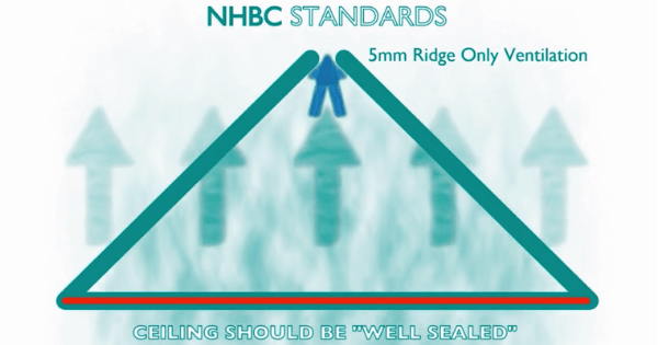
In addition to the 5mm ridge ventilation, the ceiling must also be "well sealed" as defined in BS9250.
Aside from the obvious requirements like not having any gaps or cracks in the ceiling, this standard sets air leakage requirements for hatches, and down lighters and requires sealing of service penetrations using “suitable proprietary products”, all of which can complicate the design and construction process and potentially introduce unforseen costs and delays.
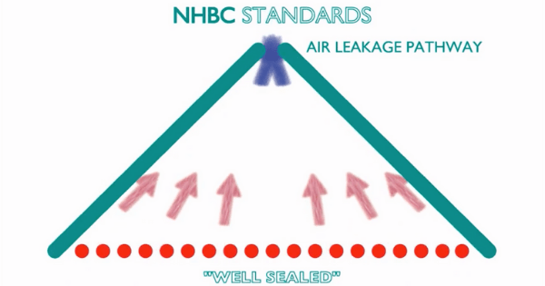
Another concern here is that by introducing a 5mm gap at the ridge, there is an additional pathway for water ingress, both during construction and in the event of damage to the primary roof covering.
This means the roof cannot be considered watertight until the roof covering is completed delaying works on internal finishes and services that could otherwise be started.
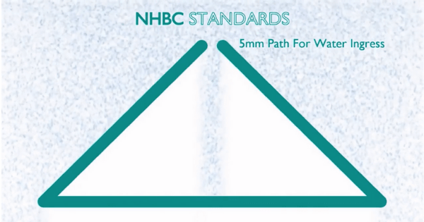
Finally, this gap means the roof is not airtight, negating the energy performance benefits used as a selling point by airtight underlay manufacturers.
It also places a lot of emphasis on the quality of the ceiling installation, which can be an issue if electricians, plumbers, ventilation installers etc are not aware of the specific requirements of BS9250.
So given these issues with the NHBC guidance, is there a way we can avoid this?
The same NHBC document includes an exemption to these rules, however this is not referenced in the main NHBC standards documents so may not be immediately apparent.
The way around adding the ridge ventilation is to use an air permeable membrane carrying appropriate certification. This allows the use of completely unventilated roof constructions.
Our Roofshield membrane is BBA certified as air permeable, and therefore qualifies under this exemption, and can be used without ventilation or vapour control as detailed in section 7 of the certificate.
For the avoidance of doubt we have written clarification from the NHBC that this is the case.
Testing
There is a sound basis for this difference between airtight and air permeable membranes, and the testing to back it up was conducted in the early 2000s at BRE scotland.
The partners in innovation (PII) project “Improved Thermal and Moisture Performance of Pitched Roofs” was undertaken by the BRE and Glasgow Caledonian University and completed in 2004.
The aim was to test and model the performance of different types of LR underlay and compare these results to conventionally ventilated roofing. A variety of test rigs were used to simulate conditions in a variety of roofs, but here we’re going to focus on the worst case result, from tests where the condensation risk was elevated as high as possible.
The four test cases were as shown here, and prior to testing, all four test rigs were pressurised, to determine the equivalent ventilation openings that would be necessary to replicate the air leakage characteristics of the unventilated roof.
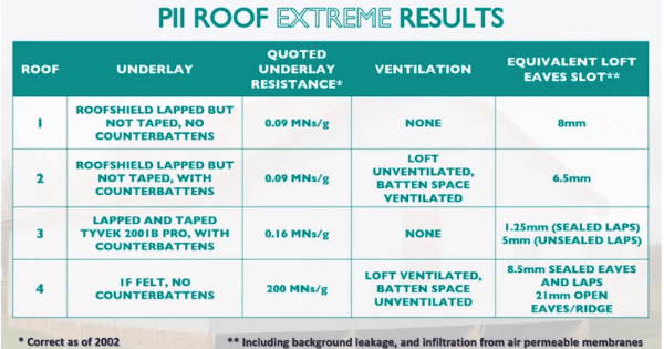
In the worst case test, not only were the loft hatches unsealed, but they were left open, and the moisture load increased using heated water baths to simulate an open hatch in a humid bathroom environment. The combined effect of this is to raise the temperature and the vapour pressure in the loft, making it more likely that condensation problems will occur.
During the extreme test period, heavy condensation was noted on the underside of both the airtight LR underlay and the traditional roofing felt while the air permeable underlay on the first pair of roofs was free of moisture.
In these roofs the air permeable underlay allows airflow through the loft, so as well as the vapour drive pushing moisture from inside to out, there are actual air changes taking place. This not only increases the ability of the roof system to transport the moisture vapour safely out of the building but makes it harder for condensation droplets to form on the roof underlay. It is because of this testing that both BS5250 and the NHBC recognise that air permeability of roofing underlays plays a significant role in reducing condensation risks in pitched roofing.
As well as condensation control, an important factor in roof design and underlay specification is the effect of wind uplift forces on the roof system, and this is covered by the code of practice for slating and tiling, BS5534.
As wind blows over a roof structure, the airflow presses on the windward side creating a downward force, the wind pressure.
On the leeward side of the roof, the airflow reduces the pressure, creating a suction which pulls the roof upwards, this is the wind uplift force.
These two forces act on the entire roof system, and the starting points of this chain of forces are the outer covering and the underlay membrane. The resistance of the uplift force is shared between the outer covering and the underlay depending on the air openness of both parts.
It follows therefore that wind uplift forces will have a greater effect on airtight systems than air permeable ones, as airtight systems will resist the flow of air by their very nature.
If the roof is not correctly designed to resist wind uplift forces then in extreme cases the tiles or slates of the outer covering can be damaged. This damage will be mainly caused by uplift forces directly removing the slates or tiles by sucking them up and off the roof. In theory it could also occur due to the underlay membrane “ballooning” and pushing them off. Although there is little if any conclusive evidence of this occurring, the 5534 standard sets criteria for underlays to resist wind forces, and divides the UK into five wind zones.
This table gives the uplift resistance force for the Roofshield membrane for each installation configuration, along with the measures that must be taken when used in a given wind zone.
As we can see here, in zones 1-3, no special measures are required at a 345mm batten spacing, however in the more extreme conditions of zones 4 and 5, designers will either need to reduce their batten spacing to 250mm, fit counter battens or tape joints.
If however they are using the traditional scottish slates into softwood sarking detail, then use is unrestricted in all zones.
So how do we determine this uplift resistance?
This the BREs wind uplift testing facility, where underlay samples are tested to determine their performance in resisting uplift forces, and the effect those forces have.
Samples are fixed into a test frame and the space below, known as the plenum, is pressurised. As can be seen here the underlay, in this case a roofing felt, will balloon upwards under this pressure. The maximum pressure that can be resisted is determined by the point at which the membrane reaches 35mm above rafter level, or is unable to sustain further pressure increases.
Here was can see the Roofshield air permeable underlay on the test rig.
Although air permeable membranes will balloon eventually, it takes a higher pressure to achieve this result as a proportion of air will flow through the membrane instead of deflecting it.
BS5534 also contains definitions of membrane types, and also specifically defines for the first what performance is required for an air permeable membrane.
Under the definition given in BS5534, an air and vapour permeable underlay must have a vapour resistance of not more than 0.25 MNs/g, and an air permeability of not less than 20 m3/m2/h.
This removes any uncertainty about whether or not an underlay can be treated as air permeable, but does not however address any effect of increasing or decreasing air permeability.
5534 also introduces new definitions on the types of ceiling, and addresses the influence of the ceiling on the performance of the roof as a whole.
This first type of ceiling, a continuous ceiling” is analogous to the “well sealed” ceiling defined in BS9250, however the definition is less prescriptive, simply stating a permeability that must be achieved.
Ceilings failing to meet this criteria are classed as discontinuous.
Discontinuous ceilings are not classed as “well sealed” as regards wind uplift zoning, and can limit the suitability of a given underlay membrane for the site conditions.
We’ll now move on to discuss a new alternative methodology for air permeability testing, pulsed air tests.
In this testing, a high pressure pulse or air was used to determine the comparative performance of an unventilated roof fitted with the Roofshield underlay, against an otherwise identical roof fitted with an airtight LR underlay and ridge only ventilation.
The testing was conducted on both semi-detached and detached properties, and in this test, the decay time of a pulse of high pressure air is measured, and this is used to determine the overall air permeability of the roof.
In both cases the Roofshield roofs are fully closed, with no openings provided at either eaves or ridge, so moisture vapour may only escape through the surface of the membrane, and any air movement is coming through the surface of the membrane rather than through any gaps.
At the time of testing, condensation was visible in the ventilated roof, where none was apparent on the underside of the roofshield under the same conditions.
In close up the quantity of condensation present suggests the ventilation is not performing optimally.
The results of the testing are shown here, and it can be seen that the non-ventilated, air permeable Roofshield roof has air change rates comparable to a conventionally ventilated roof.
The conclusion of the testing is that Roofshield provides much more uniform ventilation through the roof space rather than simply relying on passively driven cross ventilation via low level eaves vents and/or high level ridge vents or roof tile vents, allowing water vapour to leave the roof space through the membrane without requiring the vapour to be carried in moving air.
This confirms previous testing which has concluded repeatedly that non-ventilated roofs with air permeable underlays perform at least as well as, and more often better than, conventionally ventilated roofs, and do not suffer from condensation problems associated with airtight LR underlays used without ventilation.
The final testing topic we’ll consider is nail sealing against water ingress.
Nail sealing
There has always been a concern when using breathable fabrics that water may track into the roof through holes made by fixings, particularly if the membrane is not draped to provide a runoff channel. To put this concern to the test, nail sealability testing has been conducted on the roofshield membrane.
In this test, a sample of the Roofshield membrane is mounted into a test frame, the upper chamber of which can be filled with water to introduce a hydrostatic head.
The test sample is perforated with nails, to simulate, for example, counter batten fixings being made through the membrane.
Once the nails are in place, the upper chamber is filled with water and the rate of water ingress, or not, into the lower chamber is assessed. In the nail sealability testing case no water is able to penetrate through the fixings into the lower chamber.
Seen in the cross section under a microscope we can see how this sealing process works. The nail does not make a physical hole through the membrane but rather separates the microscopic fibres around the fixing. These fibres then clench tight around the shank of the nail, forming an effective seal around the fixing, provided the nail remains in place.
Roofshield roofs are fully closed, with no openings provided at either eaves or ridge, so moisture vapour may only escape through the surface of the membrane, and any air movement is coming through the surface of the membrane rather than through any gaps.