Building On Contaminated Land - A Proctor Group

Please contact us via contact@construction-cpd.com to get permission to publish this video on your website.
<div style="position: relative!important; width: 100%!important; min-height: 700px; overflow: hidden!important; padding-top: 56.25%!important;"><iframe src="https://www.construction-cpd.com/cpd-external-view?ExternalId=37&ReturnUrl=https://www.construction-cpd.com/building-on-contaminated-land-cpd" style="position: absolute; top: 0; left: 0; bottom: 0; right: 0; width: 100%; height: 100%; min-height: 500px; border: none;" mozallowfullscreen webkitallowfullscreen allowfullscreen></iframe></div>
VOC Barrier Membranes
Welcome to our Building on Contaminated Land: VOC Barrier Membranes Webinar.
With the increasing focus on sustainably resolving housing shortages in our cities, redevelopment of brownfield sites is becoming ever more widespread and bringing with it an increasing focus of site remediation and protecting building occupants from soil contamination.
Login to record your CPD points

Today we’re going to look at some of the common issues affecting construction on contaminated sites, particularly those affected by VOC contamination, and discuss how barrier membranes can provide effective, safe and good value solutions.
We’ll first consider what VOCs are and where they come from, before moving onto risk based design philosophy and how it can be applied. We’ll also be looking at the most common membrane types, and the pros and cons of each solution.
We’ll be finishing up with a Q&A session, so should you have any queries throughout today's webinar, you can email them to webinar@proctorgroup.com, or type them into the comment box on this video stream.
You'll be able to review this presentation and the Q&A afterwards, and you’ll be emailed links once the event concludes.
What are VOCs?
VOCs or volatile organic compounds are defined in CIRIA 716 as: "organic compounds that are volatile under ‘normal’ environmental/atmospheric conditions. They may be found in the ground in the solid,liquid and dissolved phase form as well as in gaseous phase”.
VOCs can be both man made or natural and have a wide range of applications and sources, being found in everything from paints and coatings to plastics and cleaning products. Hydrocarbon fuels such as petrol and diesel are also forms of VOC.
While not all these compounds are harmful, anthropogenic - man made - VOCs are regulated to limit exposure to those that are. In construction, the VOC content of products such as paint is restricted to ensure the detrimental effects on indoor air quality and the health of building occupant are limited, and VOCs originating from contaminated land or other external sources are similarly regulated. VOC contamination can severely reduce the amenity of the building or structure, with particularly severe effects on sufferers of asthma or other respiratory issues. While some effects such as dizziness can be mild and short term, contaminant vapours can also have carcinogenic effects or cause damage to liver and kidneys given long term exposure. These effects can also be present during remediation works, and therefore exposure of site workers during remediation works is also an important consideration.
Sources of VOC Contamination
Naturally occurring VOCs are typically quite rare compared to other natural soil gases such as methane or carbon dioxide, so in most cases building designers will be dealing with pollutants arising from the historical uses of sites.
Most commonly this will mean former industrial sites where chemical spillage may have occurred, or where poor waste handling practice has led to discharge into the environment. Sites such as former petrol stations or residential sites with fuel oil storage tanks can also require remediation to remove VOC contaminants.
Risk Based Design
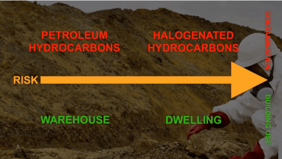
The most appropriate strategies for dealing with these contaminants will depend on the precise nature of the pollutants present on the site and the building’s intended use.
For example, petroleum hydrocarbons such as benzene, toluene or diesel fuel can, given certain soil conditions, attenuate more readily than the types of halogenated hydrocarbons found in dry cleaning fluid and hence may present a lower risk. Likewise, a warehouse or storage facility will require a less rigorous approach to remediation than a dwelling or office, all else being equal.
These risk factors are both numerous and complex, and the CIRIA 716 Guidance Document outlines the processes involved in both assessment and mitigation.
The first stage of this process is the development of a conceptual site model or CSM.
Based on information obtained from both historical desk studies and direct site measurements, the CSM identifies the potential hazards present on a site and their likely effects on subsequent human activity during construction and afterwards, as well as the implication for future development.
Once complete, the CSM for the basis for a succession of increasing detailed risk assessments as the project progresses. This approach allows the remediation to be undertaken in the most efficient way possible. Some forms of remediation such as removal of the pollution entirely can be difficult and expensive, and by ensuring this is not undertaken unless required, a robust, safe and economical solution can be achieved through good design.
Pollutant Linkages
The primary concept considered in these assessments is that of “pollution linkages”. These are chains of risk factors that taken together, present a risk to health and/or safety. If however, parts of the chain are removed the resultant risk factors can be reduced or eliminated.
The primary linkages present in every situation are the pollution source, the pathway, and the receptor. This source pathway receptor model forms the foundation of risk based design strategies for ground gas and VOC contamination.
Source
Source treatment involves taking action to break the linkage at the source, the actual pollutant itself. In very simple terms this involves achieving one of the following outcomes:
Destruction/Neutralisation, whereby the pollutant is rendered harmless through the use of some form of treatment such as adding a degrading chemical agent or a process such as heat.
Removal, which can entail either removal of the polluted soil and disposing of it off site, or extracting the pollutant from the soil.
Immobilisation, or “trapping” the pollutant by adding chemicals to solidify the contaminants, making it impossible for liquids or vapours to escape.
Pathway
A pathway management solution breaks the link between the contamination at the source and the building occupants by two primary means:
- Barrier systems, which physically block the passage of harmful liquids or vapours either at the source or the receptor
- Dilution/Dispersal, where ventilation systems are used to reduce vapour concentrations below harmful levels.
Ensuring barrier and ventilation systems work effectively over the lifetime of the building is critical. Both specification and installation of these systems is more complex than it may appear, with an array of physical properties, tests and installation details to consider. It’s also not always possible to rely on the membrane to provide a 100% barrier to contaminants, so these systems are usually used as part of a wider ranging remediation strategy.
Receptor
Receptor management is the most problematic of the three strategies, mainly as it can come into direct conflict with the purpose of the building or structure by placing restrictions on the occupants which may prove unacceptable.
For this reason, receptor management is most commonly used as a temporary measure while a longer term strategy is developed. For example, restricting access to buildings during decommissioning of an industrial site, or evacuating residential properties in response to a nearby chemical spillage.
Another more common example of receptor management would be health and safety requirements placed on contractors during remediation works, such as PPE or safe working practices.
Pathways in Practice
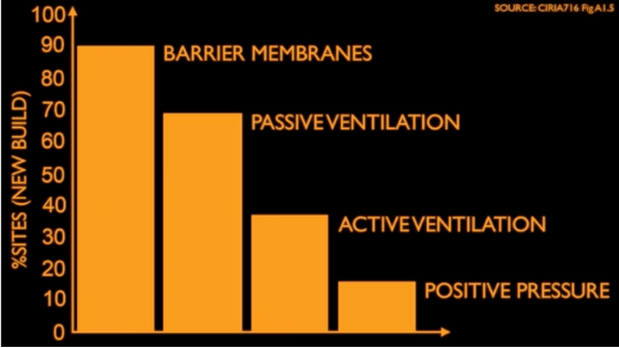
Today we’ll be considering pathway management in more detail, specifically the use of barrier membranes to restrict the flow of VOC vapour into buildings and structures. Barrier membranes strike a good balance between effectiveness, practicability and sustainability making them by far the most common solution used in new build projects on brownfield sites in the UK today.
As we briefly discussed already, these systems are commonly used in conjunction with other remediation measures such as ventilation/dispersal systems. A well designed barrier system can reduce exposure to contractors during remediation works, and reduce disposal costs associated with contaminated soils, helping to achieve the right balance of practicality and long term durability.
Membrane Specification
When specifying geomembranes for VOC applications, it’s important to remember that chemical resistance and vapour permeability are not the same thing, and membranes that are highly resistant to liquid VOCs may not be suitable in a VOC vapour barrier application. Conversely, membranes which resist VOC vapours effectively may lack the resistance to be used in the presence of liquid hydrocarbons.
That’s not to say the chemical resistance is not important, as the barrier must be able to resist exposure to adverse conditions in the longer term without negative effects to its performance or mechanical properties. It can’t always be guaranteed that the VOCs will remain a vapour as the water table may rise and bring the membrane into contact with VOCs in liquid form.
It's therefore important to identify the most appropriate combination of physical properties for the application, however this is in turn dependent on good test data for a range of chemicals being available for the membrane specified.
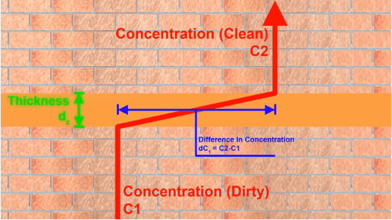
The permeability of the membrane is governed by the following factors:
- The concentration gradient between clean and dirty sides of the barrier
- The solubility of the contaminant in the membrane polymer, referred to as “partitioning”
- These two factors govern whether or not vapour transfer will occur, for example water is not soluble in HDPE, so will not permit transfer as the membrane surface will not allow its absorption.
In contrast, benzene will pass through readily.
The rate of transfer and how quickly equilibrium is reached is affected by the following factors:
- The molecular structure and thickness of the membrane
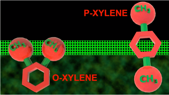
- Molecular Size/Shape
- The material composition of the membrane dictates how much free space there is at the molecular level for vapour to pass through, and how easy a pathway this provides. For example a crystalline, regular structure will permit the passage of gas more readily.
Likewise the configuration of the VOC vapour molecule will dictate how easily they can pass, some molecules being significantly more “streamlined” than others.
As we can see, having these complex relationships easily summarized is an important factor in ensuring the design is appropriately tailored to the application. Membrane manufacturers must therefore ensure this information is available and presented in standardised form to allow specifications to be easily compared and the implications for risk assessment to be fully considered.
CIRIA 748 lists the following substances as likely to require permeation testing:
- Benzene
- Toluene
- Ethyl Benzene
- M,P and O Xylenes
- Hexane
- Vinyl Chloride
- Tetrachloroethene (PCE)
- Trichloroethene (TCE)
- And Napthalene
Designers should satisfy themselves that the remediation measures specified are appropriate to the conditions likely to be encountered on individual sites.
Durability
The actual VOC resistance is only one facet of membrane performance that must be considered.
Membranes must also be able to resist degradation processes such as oxidation, particularly if they are based around foils. Once again, there is a series of linkages that must be considered as the basis of good robust design.
As part of an appropriate overall design, a membrane of lower resistance to a liquid contaminant may still be suitable provided exposure to that liquid form is minimised, for example by means of source remediation or by ensuring the barrier is located in the structure such that contact is impossible.
In our example here, if the membrane is located underneath the structural slab there is a risk the groundwater may bring contaminants from the source into contact with the membrane, which is a particular risk where the presence of water may act as a catalyst and increase the rate of degradation.
To resolve this issue, the membrane spec could be increased to improve the chemical resistance, but this may increase the cost and make installation more problematic.
It could also be remedied by removing the source altogether, but again, this solution may not be practical or economically viable.
A more straightforward solution would be to simply relocate the membrane over the structural slab, which would remove the risk of waterborne contamination in all but the most extreme flood conditions.
Under most circumstances this would be deemed an acceptable risk.
So we can see how taking a holistic view of the design criteria can lead to significant benefits, however even the best designed solution is only as good as its implementation.
Installation
Particularly when considering low permeability membranes, the physical integrity and continuity of the barrier is paramount and the membrane must be capable of resisting the physical stresses of the installation process and the in-use circumstances.
Installation and verification is therefore of equal importance to specification.
While there are some obvious commonsense considerations here such as ensuring there are no gaps or punctures in the material and all pipes and structural elements are properly sealed, there are also some other less apparent aspects to bear in mind.
As we’ve discussed already, the thickness of the membrane is an important factor as regards vapour permeability, and this also means that any factors that may affect the thickness are important.
What is less well understood is the impact this can have on detailing, due to the flexibility of membranes. Thick, bulky membranes may perform well when used in large flat areas with few complex angles, but when used in situations such as raft foundations they can be susceptible to certain problems.
Firstly when membranes are folded around tight angles, the molecular structure of the material can open up on the external side of the angle, this will effect a corresponding change in the partitioning characteristics in that area.
Studies suggest this effect can be present at angles as low as 60 degrees for some membrane types, so at the 90 degree angles most commonly associated with foundations it can have a significant detrimental effect on permeability performance.
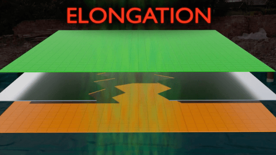
Secondly if the membrane is not fully supported at these angles, the weight of any subsequent layers, such as slab or screed, can elongate the membrane, reducing its thickness and increasing the permeability through the free space in the membrane as the molecular gaps are wider.
Taken to an extreme, both of these scenarios could even result in the membrane cracking, splitting or tearing, and in a way which would not necessarily be obvious during a site inspection.
An important aspect of installation is the sealing of joints between adjacent sheets. While welding is undoubtedly a more effective solution, it requires specialist contractors and care and attention during installation. This means that traditional taped joints are often used instead.
When taped joints are used it’s critical to ensure they are done right, as taped joints are a common point of failure in membrane systems. The correct tape as recommended by the membrane manufacturer should always be used, and the surfaces to be joined must be free from any dirt, contamination or moisture as this may adversely affect the adhesion.
It’s also worth remembering that under some circumstances, such as where membrane joints are not compressed by a slab or screed, the use of taped joints is not “considered prudent” by CIRIA.
Membrane Types
The choice of material used on site must be informed by both the permeability, chemical resistance, physical properties, and expected installation procedure.
All the possible membrane types in gas protection have pros and cons, and it’s important the properties of the material selected adequately address the risk factors present on a given site. When it comes to building on contaminated land, there are no magic bullets or one size fits all solutions.
So now let's look at some of the most commonly used geomembrane types.
- Polypropylene or PP
- PP membranes have good elongation characteristics, and are highly flexible. This makes them a good choice where settlement is likely or where complex detailing must be undertaken.
- PP is however relatively permeable to most gasses and is expensive. PP membranes also have poor adhesion characteristics and therefore require specialist welded joints rather than tape jointing.
- PP membranes are traditionally used in water containment applications, due mainly to its suitability for use on larger unreinforced areas
- Hexane
- Vinyl Chloride
- Tetrachloroethene (PCE)
- Trichloroethene (TCE)
- And Napthalene
- High Density Polyethylene (HDPE)
HDPE is cheaper, and offers good resistance to puncturing, but in comparison to PP is rigid and therefore both difficult to install on complex details and prone to stress cracking. Any bending of the membrane to angles over 60 degrees is typically not recommended due to it’s detrimental effect on performance. Because of this mechanical weakness, HDPE is better suited to large uninterrupted floor areas, which is a good fit with the roll sizes they are typically supplied in.
Like PP, HDPE membranes should not be tape jointed and require specialist welding contractors and verification.
Low Density Polyethylene (LDPE)
LDPE membranes are “standard” DPM materials, which are cheap, easy to handle and readily available, but can be low-quality and are generally not suited for gas resistance applications due to their high permeability and limited resistance to damage and UV. LDPE membrane’s resistance to VOC transfer is particularly poor, and these membranes can degrade rapidly if directly exposed to chemical contamination.
Low grade LDPE can also have problems with manufacturing tolerances, resulting in a material that while water resistant if undamaged, will not deliver consistent and robust performance in gas protection applications.
Reinforced Virgin LDPE
Reinforced membranes made from higher quality virgin LDPE are inherently more consistent as good control of thickness and material tolerance is critical for achieving a good lamination with reinforcement. This reinforcement also greatly improves the membranes resistance to tearing and damage while allowing the membrane to retain its flexibility.
This results in a good balance of durability, performance, ease of installation and cost. It is however important when using these membranes to have a good understanding of the risks present on-site to ensure the vapour or gas permeability of the membrane is adequate for the application.
Foil Based Membranes
Adding a foil core to LDPE or HDPE membranes dramatically increases the gas and vapour resistance of the membrane without a correspondingly dramatic cost increase. This makes them a good option where elevated risks are present and it’s not feasible or desirable to use source remediation to lower the concentrations present.
There is a common misconception that because the membrane has an aluminum foil in it’s build up that this will offer good all round protection from contaminants. While that may be true when considering ground gasses, there problems with this assumption, particularly when VOCs are involved.
The first problem is the reduction in performance over time caused by oxidation of the foil layer, this can either be caused by damage to the membrane, by exposure to chemical contaminant levels-out with its design specification or at the edges of membrane sheets where the foil is exposed.
Another problem is common on all sites where foil membranes are used, regardless of the presence of VOCs. While the base plastic membranes are able to elongate to some extent, this is not true of the foil layer within them. If settlement occurs the corresponding stretching of the membrane can rupture the foils leading to a significant deterioration in gas barrier performance.
Login to record your CPD points
It's therefore critical when using foil based membranes to make sure settlement is minimised, and expansion joints are properly detailed to avoid overstressing the membrane.
Foil membranes such as the A. Proctor Group’s Protech GM Super are generally considered a better fit for common ground gas applications such as methane and landfill gases, when dealing with VOC contamination a dedicated membrane such as Protech VOC Flex will offer a more comprehensive solution.
Specialist Film Laminate Membranes
These types of membranes are similar to foil core membranes as above, but replace the foil with a specialised plastic film such as EVOH. This allows the performance of the membrane to be adapted to meet application specific barrier requirements.
EVOH membranes offer good resistance to a variety of VOC contaminants while still allowing the membrane to retain good physical performance characteristics such as flexibility and elongation.
Liquid Applied Membranes
Liquid applied membranes are ideal for complicated foundation detailing and uneven surfaces. The downside to these systems is that it’s not always easy to determine the tolerance of application, such as continuity or thickness of coating.
Liquid applied systems do however make a good companion to sheet membranes where complex details must be sealed.
Summary
So we’ve seen throughout today's presentation that the most important factor in dealing with contaminated sites is good design based on good information. Whether it’s conducting a thorough investigation into the historical uses of the site or ensuring the correct membrane for the job is well installed by contractors, a good understanding of the risk factors involved and a well developed holistic remediation strategy is key to achieving a safe and good value solution.
With over 20 years experience in ground gas protection, the A. Proctor Group have always taken this approach, supplying both a range of fully tested membranes, and comprehensive technical support and design consultation throughout the specification and installation process.
(https://www.proctorgroup.com/building-on-contaminated-land)